Overview
Optics have thresholds for how strong or weak of a light level they can receive before they'll theoretically fail
- The purpose of this page is to help estimate if a particular optic will work on a particular fiber span
- Other factors, such as optical signal-to-noise ratio, reflections, and dispersion, are important and impact your optical performance but are not discussed here
Terminology
- Power level
- The power level from optics is measured in microwatts but converted to dBm for ease of reading by humans
- dB is on a logarithmic scale
- The higher the dBm the stronger your receive level
- The lower the dBm the weaker your receive level
Milliwatts to dBm Conversion
Milliwatts to dBm conversion table and some examples (rounding happening on some examples)
- Note! Not shown: LR, ER, and ZR max receive levels are not shown here.
Power in milliwatts Power in dBm 1310 and 1550 10G Optic Examples 10 10 9 8 7 4 6 5 4 2 3 2 1 Transmit minimum for some 10G ZR optics (80km) 1 0 -1 Transmit minimum for some 10G ER optics (40km) -2 -3 -4 -5 -6 -7 -8 Transmit minimum for some 10G LR optics (10km) -9 0.1 -10 LR ER ZR -11 ~6dB power budget ~11dB power budget ~23dB power budget -12 -13 -14 Receive minimum for some 10G LR optics (10km) -15 Receive minimum for some 10G ER optics (40km) -16 -17 -18 -19 0.01 -20 -21 -22 -23 Receive minimum for some 10G ZR optics (80km) -24 -25 -26 -27 -28 -29 0.001 -30
Estimates
- Ballpark estimates:
- 0.25dB loss per kilometer for 1550nm
- 0.5 dB loss per kilometer for 1310nm
- 0.3 dB loss per connector
Tools & Resources
DOM
See our knowledge base page Optical: Digital Optical Monitoring (DOM)
Command line tools to see reported RX and TX light levels of and optic inserted in a router or switch and current levels
Vendor Docs
You should also be able to search your optical vendor's documents to find the rx and tx thresholds for each model optic
RECEIVE MIN. -23.00dBm
RECEIVE MAX. (RECEIVER OVERLOAD) -8.00dBm
TRANSMIT MIN. 0.00dBm
TRANSMIT MAX. 5.00dBm
POWERBUDGET (DB) 23 dB
OTDR
An OTDR is always preferred to accurately determine your path's loss
The calculations performed on this page are intended to help when you don't have an OTDR test to rely on
Power meter
Tool used to report the current light levels (dBm) being received
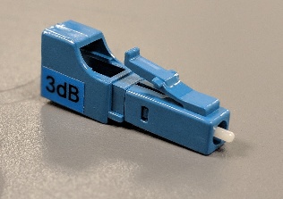
Pads/Attenuators
It's best to use the right fiber optic for your fiber span but you can use an attenuators to bring the receiving laser light within the specified receive range of your optic
- You can damage optics when operating outside of the specified maximum receive spec! Never run an optic outside its manufacturer define receiver maximum.
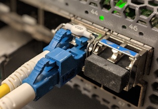
Always pad optics on the the rx (receiver) ports of your optics
One pad on the rx port of the hub interface, one pad on the rx port of the cpe interface
The RX port on an optic should be the right-hand side if the lever is facing up
Example images:
Calculating Loss
- Record the TX power of your optic
- Either by using DOM or a power meter
- Subtract the OTDR results (loss in dB)
- If you don't have OTDR test results, subtract the estimated loss based on the distance
- Subtract the connector loss (number of patches)
- Results
- Is the result within your optic's receive min -> max?
- If it's above the max RX add the appropriate pad
- If it's below the max RX you might need a different optic or
- Is the result within your optic's receive min -> max?
Example:
- My optic is transmitting at +1dBm
- I don't have an OTDR, but the fiber path distance is 27km
- Subtract 0.25dB loss per kilometer for 1550nm at 37km, subtract 9.25dB
- I'm using two patch cables, one on each side of my fiber span, subtract 1dB
- Result: −9.25dBm
- My result of -9.25dBm is within the -8dBm to -23dBm receiver specifications for the optic
- My optic should work, but as always I should check DOM post install to verify